
STEEL CORD CONVEYOR BELT SPLICING
STEEL CORD CONVEYOR BELT SPLICING - STEP BY STEP
To get the most out of this page, you may first watch the animation on the left.
Then you can follow the step-by-step instructions.
Each third of the instructions is followed by a video of real splicing works for better understanding.
For high-class splices, an air-conditioned, dust-free assembly hall with a modern vulcanization device, fresh and suitable (unvulcanized) splicing material, and experienced engineers and splicers who carry out the work in accordance with the instructions of the conveyor belt manufacturer, are required. Work disruptions must be avoided.

The components of a steel cord conveyor belt splice:
1) Cover sheets.
2) (optional) Additional reinforcement embedded in unvulcanized core rubber. It is applied like a second core rubber sheet.
3) Core rubber sheets.
4) Steel cords with original core rubber.
5) Intermediate rubber strips.

Setup of the working table.
For positioning of the bottom platen(s) of the curing press both belt ends are folded back.
The bottom part of the vulcanizer can be used as a working table.

The belt ends have to be tensioned as much as possible to avoid sag.
Both lengths will be laid one on top of the other over the whole splice length. If it is necessary to shorten the belt(s), a wedge-shaped strip of approx. 20 mm width is cut out of the upper cover so that the steel cords become visible. The steel cords will be cut with a special cutting tool.

The belt centre is marked on both belt ends and also at a minimum of three other points that are approx. 1500 mm (5 feet) apart. These centre points are then joined into a centre line using a chalked string.
Approximately half a metre behind the splice area a crossline is drawn at right angles to the centre line as a reference line.
One marked belt end is placed on top of the other marked belt end. The centre lines on each end must be precisely aligned.

The cover is cut transversally down to the cables. The knife is held at a 45° angle. The rubber edges are removed.

By means of a tensioning tool the cover is removed, supported by a knife that cuts between the cover over the steel cords.
Do not tear the cover off!
The procedure is repeated for the bottom sides of the belt ends.

The rubber between the steel cords is removed.
The cords should be carefully buffed with a grooved rotary wire brush. They remain completely covered by rubber after this procedure.
Buffing dust is to be swept off.
The steel cords will be slightly coated with a special rubber solution, and allowed to dry completely. Do not use too much of the solvent; remember it is not glue but just a confectioning aid.

An unvulcanized cover rubber sheet is placed at the bottom of the splice on top of a separation cloth.
The cloth should be approx. 300 mm (12 inches) longer in the longitudinal directions.

The alignment is checked again.

The steel cords have to be positioned as determined by the belt manufacturer or by the standard (f.i. DIN 22131).
See also here.

By the way: No cable has contact to any other cable.

All gaps between the cables are carefully filled with intermediate core rubber up to the height of the cables.
The entire splice area will be sparingly coated with rubber solution and allowed to dry completely.
Rubber edges are applied on both belt sides, coated with solution and dried well. The edges are tapped thoroughly with a mallet. Protruding rubber is cut off. The straightness of the splice is doublechecked.

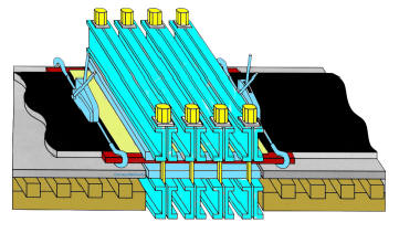
Traverses
Heating platen
Metal sheet
Separation cloth
Steel cord conveyor belt
Separation cloth
Metal sheet
Heating platen
Traverses
Edge bars, approx. 1 mm thinner than the belt, are placed against both belt edges and clamped outside the splice area.
The bars are 1-2 mm (1/16 inch) thinner than the belt.
Upper platens are placed and aligned.
End locking bolts are tightened slightly.
Oil pumps will be connected to upper traverses.
End bolts are tightened thoroughly.
Electrical cables are connected to the heating platens.
A pressure of approx. 10 bar (150 psi) is applied with oil pumps.

The vulcanization is initiated by plugging the heating platens in. Pressure will be increased as temperature rises.
Temperature is regulated by self-controlled heating platens or by switching energy on and off. After several minutes allow temperature to rise to 142°C (290°F). The curing time counts when temperature reaches 142°C (290°F). Disconnection at 145°C (295°F). Plugging-in again when temperature drops to 142°C. After curing time has elapsed, platens will be allowed to cool down to 80°C (150°F).
Please use the appropriate figures of your belt supplier!

Dismantling of Press:
Traverses and end bolts will be loosened and removed.
Upper heating platens will be removed.
Edge clamps will be loosened and removed.
Spliced belt will be lifted and lower heating platens are removed.
Working platform will be removed.
Rubber overflow at both edges will be trimmed off.
Belt surface, ramps and edges are being inspected visually.
Belt is put into service.

And don't forget to have a break - at the right time at the right place...!