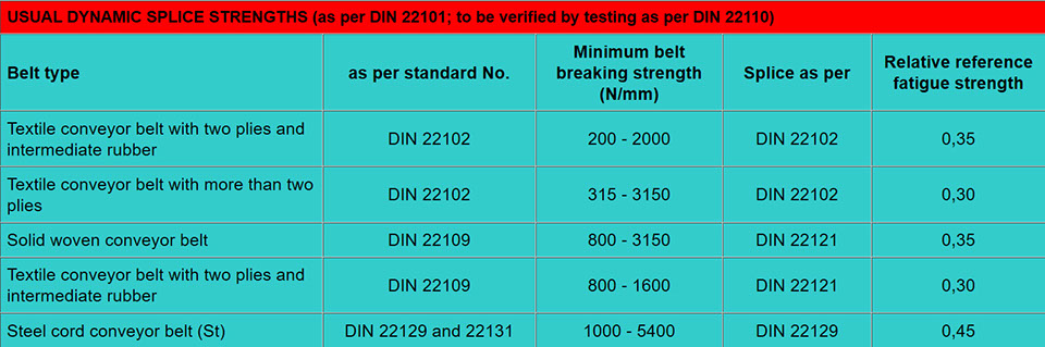

ENGINEERING TABLES


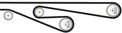
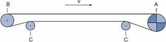
Single drive with head discharge
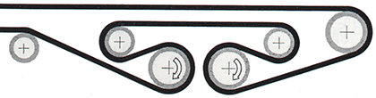
Two drives with head discharge
Two drives with advanced discharge
Two drives with head discharge

Single drive with advanced discharge

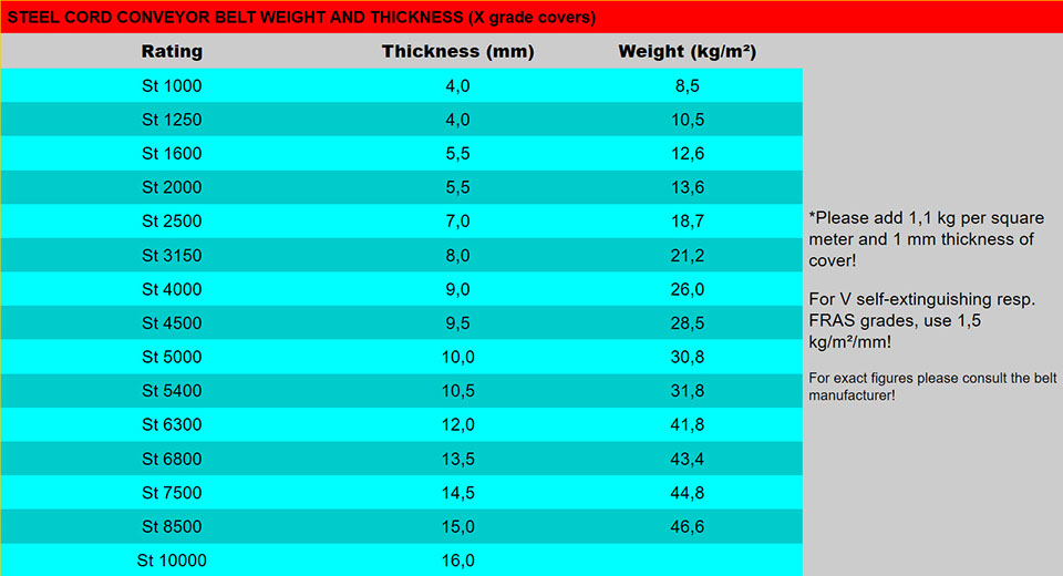
Belt Rating
St 630
St 1000
St 1600
St 2000
St 2500
St 3150
St 3500
St 4000
St 4500
St 5000
St 6300
St 7500
St 8500
St 10000
Top/bottom (mm)
6/4
6/4
8/6
8/6
10/8
10/8
10/8
12/8
12/8
12/10
12/10
12/10
14/10
14/10
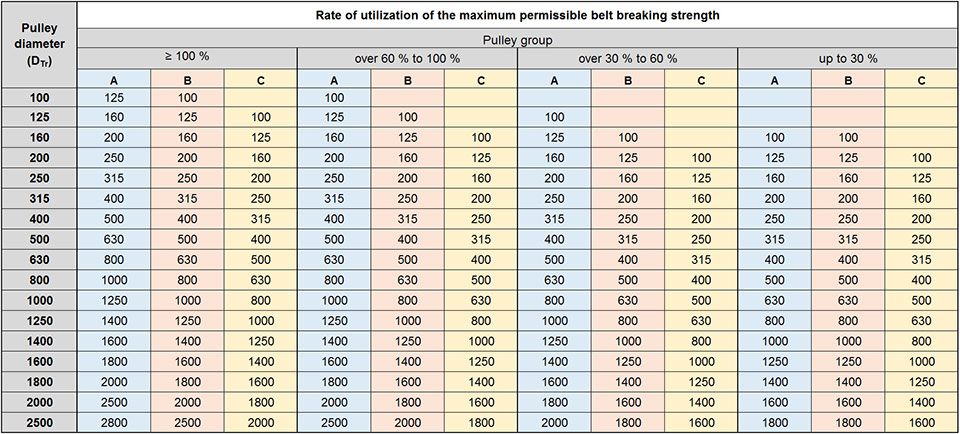
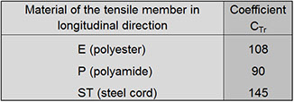
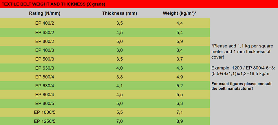
Calculation example (DTr = CTr x dGk)
EP belt (CTR = 108) x carcass thickness (7 mm) = 756 = 800 mm pulley
MINIMUM PULLEY DIAMETERS (in mm, without lagging)